Buck Boost Schematic What Every Engineer Should Know About B
High power inverting buck-boost converter circuit design with tl494 ic Buck boost converter dc circuit 555 timer schematic inductor circuits homemade circuitos electronoobs Analysis of four dc-dc converters in equilibrium
Buck Converter Simulation: Power Design- Power Electronics News
Buck converter schematic power supply figure electric simulating notes Buck converter simulation: power design- power electronics news Buck boost converter design
Buck converter equivalent
Buck booster schematic typicalSchematic diagram of buck, boost, and buck-boost converter: (a) buck Advantages of buck-boost convertersBasic circuit of buck-boost converter.
Buck boost autotransformers basic information and tutorialsBuck boost converter dc circuit arduino pwm electronoobs nano schematic circuits homemade voltage regulator potentiometer saved circuitos Buck-boost converter, based on half-bridge igbt modules with driversSchematic of buck boost converter.

Circuit diagram of buck-boost converter figure 2. equivalent circuit
Schematic of buck boost converterSchematic of a buck-boost converter . Buck converter boost circuit inverting ic high tl494 powerTl494 buck converter boost circuit diagram power based inverting high ic circuits electronic shown working below simple.
High power inverting buck-boost converter circuit design with tl494 icConverters dc analysis basic converter equilibrium figure four articles Boost buck converter schematic advantages convertersXl6009 buck boost schematic.

Converter buck circuit boost dc ac diagram converters working equivalent analysis equilibrium applications evaluation theory articles four allaboutcircuits ckt modelling
Buck converterBuck converter dc schematic circuit arduino electronoobs diy capacitor feedback using circuitos schematics circuits tut tutorial homemade lm2576 input make Buck boost converter circuit labelsSimulation schematic. (a): conventional bidirectional boost-buck.
Dc to dc buck converter circuit homemade arduinoDc to dc buck-boost converter circuit homemade Buck boost schematicWhat is buck converter? operating principle and waveform representation.

Hybrid muxing buck-booster for load-sharing : r/askelectronics
Buck boost converter designDc to dc buck-boost converter circuit homemade Xl6009 buck boost schematicBuck converter.
Buck boost circuit diagramBuck boost Analysis of four dc-dc converters in equilibriumRegulated buck-boost dc dc converter circuit – electronics projects.

Ltc3442 buck boost converter circuit
Buck-boost schematic.png -Transformer wiring diagram explained Buck boost converter bridge igbt driversThe schema of buck-boost controller.
Schematic of buck boost converterBuck transformer voltage windings versatility Buck converter graphWhat every engineer should know about buck-boost converters.


Buck Converter Simulation: Power Design- Power Electronics News

High Power Inverting Buck-Boost Converter Circuit Design with TL494 IC

What is Buck Converter? Operating Principle and Waveform Representation

Buck Boost Circuit Diagram

Buck Boost Schematic
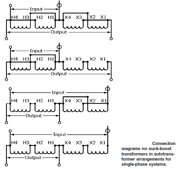
BUCK BOOST AUTOTRANSFORMERS BASIC INFORMATION AND TUTORIALS

The schema of buck-boost controller | Download Scientific Diagram